Announcement

Collapse
No announcement yet.

1985 5.8l engine wiring diagram

Collapse
X
 
  • Filter
  • Time
  • Show
Clear All
new posts

    1985 5.8l engine wiring diagram

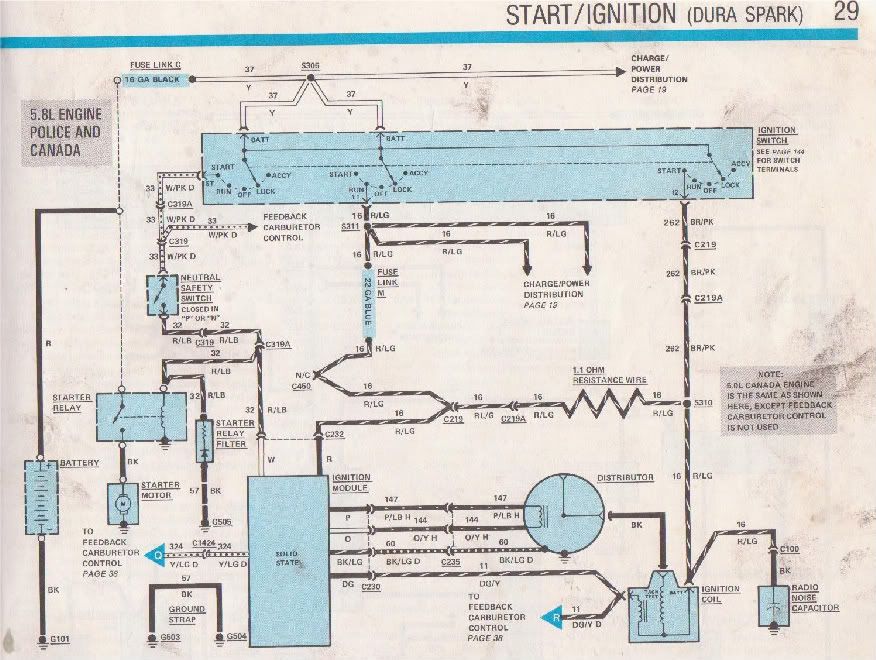
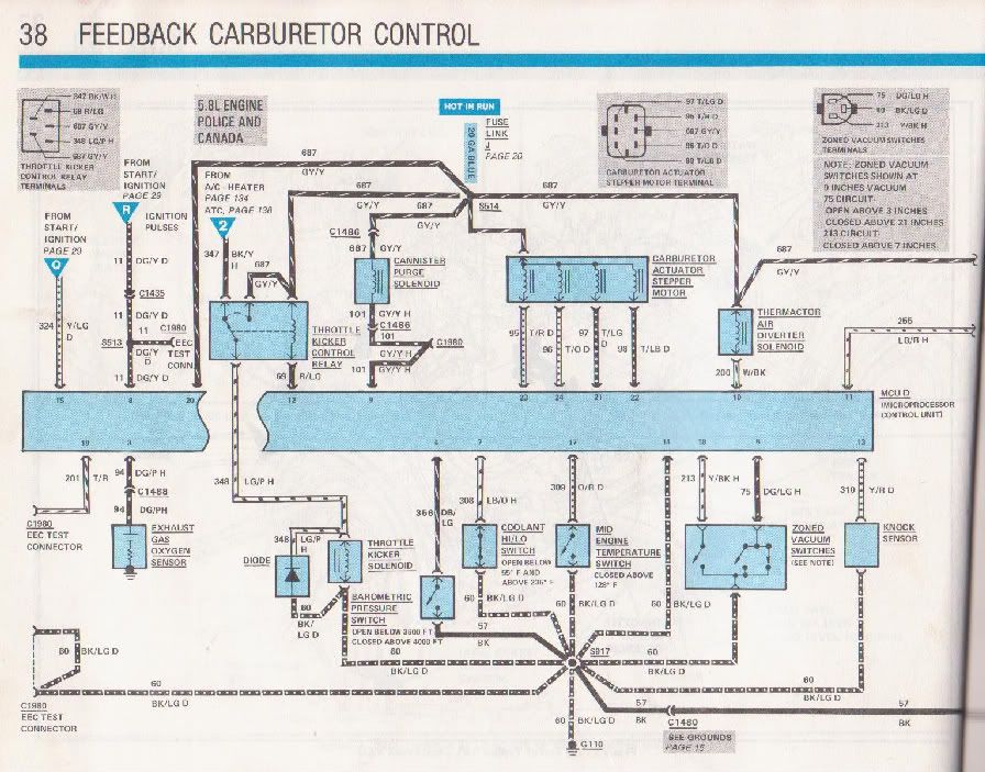
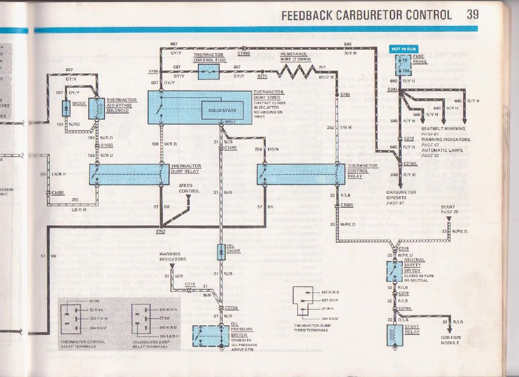
    does any one have the engine wiring diagram for a canadian 1985 351w crown vic?
    mostly need the specifics for the ignition module as mine has 3 connectors and i would like to know what evey wire does.


    thanks.

    #2
    I can get you a scan of that in a couple days, it's not with me right now but I have a 1985 EVTM and happen to own an 85 351W canadian model vic.

    85 4 door 351 Civi Crown Victoria - Summer daily driver, sleeper in the making, and wildly inappropriate autocross machine
    160KMs 600cfm holley, shorty headers, 2.5" catted exhaust, 255/295 tires, cop shocks, cop swaybars, underdrive pulley, 2.73L gears.
    waiting for install: 3.27's, Poly bushings, boxed rear arms, 2500 stall converter, ported e7's, etc

    06 Mazda 3 hatch 2.3L 5AT (winter beater that cost more than my summer car)

    Comment


      #3
      cool thanks. a previous owner had the carb replaced with a normal 2bbl ford carb insted of the variable venturi one som im just tring to figure out if he changed the ignition system as well, it all looks stock but I cant figure out 1 connector on the module. on the bosy harness side the wires are both bight red almost a pinky purple and the same coloure wires are on a small connector at the starter solinoid, but i would like a diagram to confirm this so I know the correct ignition module is in the vehicle.

      Thanks. Im in calgary by the way.

      Comment


        #4
        The ignition module itself will likely have a brown plastic piece where the wires go into it if it is stock. A picture is worth 1K words....

        Comment


          #5
          Click image for larger version

Name:	DSC00259.jpg
Views:	1
Size:	122.1 KB
ID:	1265728Click image for larger version

Name:	DSC00260.jpg
Views:	1
Size:	110.6 KB
ID:	1265729Click image for larger version

Name:	DSC00261.jpg
Views:	1
Size:	113.1 KB
ID:	1265730

          Comment


            #6
            Im also trying to figure out how to set the timming, as you can read in the previous pic of the under hood instructions im supposed to disconnect 1 of the connectos and jump it, which one am i supposed to do as 2 connectors match the descriptions.
            also what is the 4th connector that is not connected to anything for it just goes into the body harness.

            Click image for larger version

Name:	DSC00255.jpg
Views:	2
Size:	121.2 KB
ID:	1265731Click image for larger version

Name:	DSC00256.jpg
Views:	2
Size:	104.5 KB
ID:	1265732Click image for larger version

Name:	DSC00257.jpg
Views:	2
Size:	118.4 KB
ID:	1265733Click image for larger version

Name:	DSC00262.jpg
Views:	1
Size:	108.3 KB
ID:	1265734Click image for larger version

Name:	DSC00263.jpg
Views:	1
Size:	80.3 KB
ID:	1265735Click image for larger version

Name:	DSC00264.jpg
Views:	1
Size:	126.0 KB
ID:	1265736Click image for larger version

Name:	DSC00265.jpg
Views:	1
Size:	102.8 KB
ID:	1265737Click image for larger version

Name:	DSC00266.jpg
Views:	1
Size:	72.2 KB
ID:	1265738Click image for larger version

Name:	DSC00267.jpg
Views:	1
Size:	100.3 KB
ID:	1265739
            Last edited by curtklze; 08-18-2011, 10:04 PM. Reason: more info

            Comment


              #7
              Originally posted by curtklze View Post
              Im also trying to figure out how to set the timming, as you can read in the previous pic of the under hood instructions im supposed to disconnect 1 of the connectos and jump it, which one am i supposed to do as 2 connectors match the descriptions.
              The connector with the white and ?yellow? wires coming from the module is the one you jumper. The other one (white and red) is your power. Unplug that one and the engine will not run.

              Comment


                #8
                thanks for the info.

                I would still love to have the proper wiring diagrams for future wiring concerns and upgrades though.

                Comment


                  #9
                  http://cgi.ebay.com/ebaymotors/1985-...6#ht_866wt_939
                  It is worth the $25....

                  Comment


                    #10
                    Sorry for the delay, here are the scans:

                    note that "variable venturi" carbs are referred to as feedback carburetors in ford technical literature


                    85 4 door 351 Civi Crown Victoria - Summer daily driver, sleeper in the making, and wildly inappropriate autocross machine
                    160KMs 600cfm holley, shorty headers, 2.5" catted exhaust, 255/295 tires, cop shocks, cop swaybars, underdrive pulley, 2.73L gears.
                    waiting for install: 3.27's, Poly bushings, boxed rear arms, 2500 stall converter, ported e7's, etc

                    06 Mazda 3 hatch 2.3L 5AT (winter beater that cost more than my summer car)

                    Comment


                      #11
                      Originally posted by Mercracer View Post
                      The connector with the white and ?yellow? wires coming from the module is the one you jumper. The other one (white and red) is your power. Unplug that one and the engine will not run.
                      Um ... since when did we disconnect or jumper anything when setting timing on a Duraspark car?


                      OP - unless you're running the bogus standalone electronic emissions computer like my '81 originally came with, you should be able to eliminate nearly all "engine" wiring other than obvious things like the ignition system, useful temp senders, and electric choke if so equipped. Then you'll have no need for an engine wiring diagram.

                      Future upgrades will involve either a four-barrel or sequential fuel injection, so any VV learning will probably be of a purely academic nature.
                      Last edited by 1987cp; 09-02-2011, 03:19 AM.
                      2012 Mazda5 Touring | Finally working on the LTD again!

                      Comment


                        #12
                        Originally posted by 1987cp View Post
                        Um ... since when did we disconnect or jumper anything when setting timing on a Duraspark car?
                        .
                        This is only on the VV cars with the separate ECM.

                        Comment


                          #13
                          thanks for the diagrams.
                          My 351 has a motorcraft 2100-2150 2bbl from a truck (i think), it no longer uses the engine computer, but the ignition module is still hooked up to it. I think I will just get a regular truck module in the future.

                          The throttle linkage on the carb was for a truck with a c6 (i belive) so the kickdown rod wasnt working properly and my shifts were shit, so I went to picknpull and checked out 3 different 351 panthers, 1 had been converted to a 2150 just like mine but the throttle shaft linkage was identical to the vv carbed 351's, so I bought the carb and a kick down rod from a clean 81 grand marq with a 351 vv carb.

                          I just swapped the throttle shafts from the donor carb to my carb and replace the kick down rod (i bent mine to shit trying to get it to work), then set the idle mixture screws (they were set wron from a bad install job), base idle and timing (16 deg befor tdc for some extra kick), then set the tranny TV rod by measuring the pressure and adjusting the kick down rod screw at the throttle, 0 psi in neutral at idle and 32-35 with a 10mm spacer inbetween the adjuster screw and throttle at idle.


                          also I measured my sway bars, front is approx 27mm rear is approx 17.5mm (need som addco bars )

                          Comment


                            #14
                            Originally posted by Mercracer View Post
                            This is only on the VV cars with the separate ECM.
                            Except that he's apparently running a 2150 with Duraspark.

                            Or ... are you saying that the bogus add-on emissions computer intercepts the ignition trigger signal somehow? Granted, I hardly paid a particle of attention to how that was hooked up when I removed it from my '81, but I do seem to recall that the emissions wiring was entirely standalone, with the ignition wiring integrating only with the 1G alternator stuff (oddly enough).


                            OP: What's wrong with your Duraspark module?
                            2012 Mazda5 Touring | Finally working on the LTD again!

                            Comment


                              #15
                              Originally posted by curtklze View Post
                              thanks for the diagrams.
                              My 351 has a motorcraft 2100-2150 2bbl from a truck (i think), it no longer uses the engine computer, but the ignition module is still hooked up to it. I think I will just get a regular truck module in the future.
                              Not necessary, just unplug computer, unplug plug from computer to duraspark, make a jumper wire. And then congratulations, you have Duraspark II.

                              Comment

                              Working...
                              X